|
|
|
Follow each step below to find which towers have 3G, next5G and 4G Mobile Broadband services installed.

Using Google Earth and information available from the a number of online tools such as the Register of Radiocommunications Licenses searchable from the Australian Communications and Media Authority's Radcom website.
- Find location of Cell Tower's that service your area.
- Examine the details of these service such as : Antenna Height, Azimuth, Tilt Angle, Transmit Power.
- Filter in towers that are 3G or 4G only, towers that have a particular carriers equipment installed. e.g. Telstra Optus, Vodafone NBN co.
- Examine 4G services for MIMO configuration.
Best viewed in Fire Fox, SeaMonkey, Opera, Safari or Chrome.
(basically any browser apart from Internet Explorer)
Go back to the ONwireless eBay Store
If not already installed, download and install Google earth from the Google Earth Download page.
Hint: To speed up the download, exclude Google Chrome by unchecking the checkboxes.
|
|
Google Earth will be used to view satellite and land contour images of your location.
You'll be able to view the hills and mountains and plot a line of site path between a marker at your location to a marker at the cell tower location. |
| |
|
Fly to Your location
|
Find your GPS coordinates & mark your location
|
 |
 |
|
1.1 Google Earth >> Tools >> Options
- Configure to display Latitude and Longitude in Decimal Degrees.
- Stop GE from automatically tilting the view as it zooms.
TIPS:
A. In Win 7, use the ![[windows]](http://onwireless.com.au/images/pages/ACMA-RADCOM/ACMA-new-search/windowskey.gif) + + ![[left/reight arrow]](http://onwireless.com.au/images/pages/ACMA-RADCOM/ACMA-new-search/LR-arrow-keys.png) key combination to key combination to
auto-scale and locate the active window to a split screen.
B. Right-mouse-click the Place maker, to bring up the options
and access its properties.(On a Mac: Get Info)
|
1.2 Drop a marker at your location.
1 - Paste the Lat/Long coordinates, Press [Search].
2 -  Drop a marker near your location and drag it to Drop a marker near your location and drag it to
the exact position your antenna will me mounted.
[Add], [Place mark].
Name your Place marker for future reference.
3 - Highlight the Coordinates without the "°" and to copy to the
notes box, as shown above.
This can make for easy copy/paste in a later step.
|
|
|
|
 1.3 Leave Google Earth open. 1.3 Leave Google Earth open.
You'll be using this later, so minimize or re-size without closing it.
1.4 Save your work.
Its a good idea save your place-mark by clicking
"Save my Places" on the "File, Save" menu of Google Earth.
This saves all your work in Google Earth, so if your PC or Google Earth crashes while your doing this research, you wont need to start all over again.
|
|
| |
|
1.5 Alternatively , E-mail or Save the KMZ file in Google Earth.
|
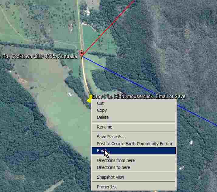
A. Drop a Place mark at your location
B. Right mouse click on the Place mark.
C. Select "Save Place As" or "E-mail".
Notes:
The ACMA uses AGD66 datum formatted coordinates whereas the coordinates accepted by Google Earth use WGS84. The an AGD66 coor'd is about 200m south east of WGS84.
|
|
|
|
|
| |
|
|
| |
Telstra Example
|
Vodafone Example
|
 |
 |
|
2.1 Check your telco's coverage.
a. Check the
Telstra,
Optus and
Vodafone coverage maps.
b. Copy and Paste your coordinates from Google Earth.
- Telstra Coverage Maps accept Lat/Long or street address.
|
2.2
Coverage estimate for your location.
- Vodafone and Optus Maps allow only valid street address.
|
|
2.3 Zoom Out to get the big picture.
- Zoom in/out to get an idea of where the Cell Towers are located.
|
TIP: Enable POP-UPS in your web-browser for onwireless.com.au to view all the content such as the Mobile Coverage Maps.
|
|
|
Find Cell Tower Services and Locations
|
The ACMA / RADCOM website has been updated with improved search functions.
You can now search for Mobile phone towers near your location by Latitude/Longitude or Post code.
The Results can be filtered by Emissions Designator, Client Name (e.g. Telstra), Frequency and much more.
Click here to open the ACMA/RADCOM website new window
|
| |
|
Fly to Your location on the search Map
|
Filter/Refine the results
|
| acma.gov.au |
 |
| |
Register of Radiocommunications Licenses |
 |
|
| acma.gov.au |
|
| |
Register of Radiocommunications Licenses |
 |
|
|
3.1 Enter your GPS coordinates.
a. Click the Zoom to Lat/Long or Post code drop down menu.
b. Select Lat/Long Decimal, (see now the reason for Step 1.1 above)
c. Copy the Lat/Long coordinates from Google Earth into the boxes.
d. Press GO!
Table 1.
Use this data to refine your search
| 3G Bands |
Emissions Designators |
Common Name
|
Low Frequency
|
High Frequency |
Telstra/Bigpond nextG
|
14M9G7W
14M9W7W
9M90W7W
9M90G7WEC
9M40W7WEC
4M90G7WEC
|
850MHz
|
824 MHz |
890 MHz |
Vodafone 3G
|
4M80G7W-- |
| Vodafone 3G+ |
TBA |
| Optus, Virgin 3G |
3M84G7W
|
900MHz
|
880 MHz |
960 MHz |
| Vodafone 3G |
3M99G7W |
| |
|
|
|
|
|
Telstra 3G
|
3M84F9W
9M90G7WEC
4M90G7WEC
|
2100MHz |
1920 MHz |
2170 MHz |
| Optus 3G |
9M68G7W--
3M84G7W--
|
| Vodafone 3G |
14M9G7WEC
|
| |
|
|
|
|
| 4G Bands |
Emissions Designators |
Common Name
|
Low Frequency
|
High Frequency |
|
Telstra 4G FDD 1800
|
15M0W7D
13M5W7D
9M90W7D
10M0W7D
5M00W7D
9M90W7DEW |
1800MHz
|
1710 MHz |
1880 MHz |
Vodafone 4G 1800
|
TBA |
| Optus 4G FDD 1800 |
10M0W7D-- |
| Telstra 4G LTE-Advanced |
TBA |
900MHz
|
880 MHz |
960 MHz |
|
|
| |
|
|
|
|
|
Optus 4G TDD 2300
|
20M0W7W-- |
2300MHz |
2302 MHz |
2400 MHz |
|
|
|
|
|
|
3.2 Filter the site results.
a. Click the Filter Sites (Filter in Use) drop down menu.
b. Select the By Assignments tab.
c. Press Update Map!
3.3 Filter Sites having Assignments usage.
With Clients where:
[Any Details] [matches] [your carrier]
[your carrier] would be Telstra, Optus, Vodafone etc.
With Licenses where: [not needed, leave blank]
With Assignments/Device Registrations where:
[Emissions Designator] [matches] [optional- blank]
If you wish to filter by Emissions Designator [optional- blank] would be 'Em Des'. Otherwise leave blank. This is handy to isolate certain services such as Optus 4G LTE 1800MHz services only.
[see Table 1.]
By Assignment/Device Registration Frequency range:
Low Frequency: [see table below] [MHz]
High Frequency: [see table below] [MHz]
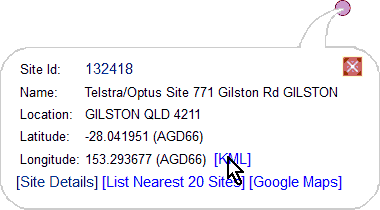
3.4 View the Site Summary, Locate tower in Google Earth.
a. Zoom and drag the map to find cell tower locations.
b. Click on the site marker  to show the Site Summary bubble. to show the Site Summary bubble.
c. Right Mouse click on [Site Details] to Open Link in New Tab

|
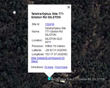
3.5 View the exact Cell Tower Site using Google Earth
|

|
 |
 |
3.5.1 - Click on the blue site marker
|
3.5.2 - Select [Open with] to automatically
open the site location in Google Earth
|
3.5.3 - View the site in Google earth |
|
|
Example Search - ACMA/RADCOM Website
This example highlights a tower with Telstra 4G LTE MIMO service:
- Two sets of Telstra services (2 sets of three Rx and sets of three Tx) between 1710-1880 MHz.
- These have Emissions Designators for 4G LTE of 15M0W7D and 5M00W7D.
- Each set of Rx and Tx antennas are at the same Azimuths, thus servicing the same areas.
Reference: ACMA
|
|
Shown below is a modified extract from the ACMA RADCOM Site Details page for the GILSTON cell tower. Intended as an example only.
Explanatory notes have been added to the right.
Click any of the live links below for more info (subject to change without notice)
|
|
acma.gov.au |
| Register of Radiocommunications Licenses |
|
| Site Details |
|
| Site ID |
132418 |
| Name |
Telstra/Optus Site 771 Gilston Rd GILSTON |
| Location |
GILSTON QLD 4211 |
| AMG Zone |
56 |
| AMG Easting |
528864 |
| AMG Northing |
6898105 |
| Precision |
Within 10 metres |
| Latitude |
-28 02 31 |
| Longitude |
153 17 37 |
| License Fee Density |
High Density Area |
|
| Assignments at this Site |
| Results 1 - 38 of 38 assignments. Sorted by Frequency. |
| ID |
Frequency |
Emission Designator |
Client |
License No |
Info from ID Details
|
BAND |
Azimuth |
Rx/Tx |
Ch# |
|
|
| 9301189 |
840 MHz |
9M90G7W |
Telstra Corporation Ltd |
9263433 |
Telstra nextG (3G) |
850 |
0° |
RECEIVE |
1 |
|
| 9301190 |
840 MHz |
9M90G7W |
Telstra Corporation Ltd |
9263433 |
Telstra nextG (3G) |
850 |
100° |
RECEIVE |
1 |
|
| 9301191 |
840 MHz |
9M90G7W |
Telstra Corporation Ltd |
9263433 |
Telstra nextG (3G) |
850 |
240°
|
RECEIVE |
1 |
|
| 9317166 |
885 MHz |
9M90G7W |
Telstra Corporation Ltd |
9263433 |
Telstra nextG (3G) |
850 |
0° |
TRANSMIT |
1 |
|
| 9317167 |
885 MHz |
9M90G7W |
Telstra Corporation Ltd |
9263433 |
Telstra nextG (3G) |
850 |
100° |
TRANSMIT |
1 |
|
| 9317168 |
885 MHz |
9M90G7W |
Telstra Corporation Ltd |
9263433 |
Telstra nextG (3G) |
850 |
240° |
TRANSMIT |
1 |
|
| 1378019-1376147 |
894.2 MHz |
8M40G7E |
Telstra Corporation Ltd |
1136417 |
|
|
|
|
|
|
| 1390239-1382257 |
902.6 MHz |
8M40G7E |
Optus Mobile Pty Ltd |
1136358 |
|
|
|
|
|
|
| 5005250-1389764 |
902.6 MHz |
3M84G7W |
Optus Mobile Pty Ltd |
1136358 |
|
|
|
|
|
|
| 1378018-1376147 |
939.2 MHz |
8M40G7E |
Telstra Corporation Ltd |
1136417 |
|
|
|
|
|
|
| 5005249-1389764 |
947.6 MHz |
3M84G7W |
Optus Mobile Pty Ltd |
1136358 |
|
|
|
|
|
|
| 1390238-1382257 |
947.6 MHz |
8M40G7E |
Optus Mobile Pty Ltd |
1136358 |
|
|
|
|
|
|
| 9361211 |
1.7175 GHz |
15M0W7D |
Telstra Corporation Ltd |
9263447 |
Telstra 4G LTE FD |
1800 |
0° |
RECEIVE
|
1 |
|
| 9361215 |
1.7175 GHz |
15M0W7D |
Telstra Corporation Ltd |
9263447 |
Telstra 4G LTE FD |
1800 |
240° |
RECEIVE
|
1 |
|
| 9361213 |
1.7175 GHz |
15M0W7D |
Telstra Corporation Ltd |
9263447 |
Telstra 4G LTE FD |
1800 |
100° |
RECEIVE
|
1 |
|
| 9361221 |
1.7275 GHz |
5M00W7D |
Telstra Corporation Ltd |
9263496 |
Telstra 4G LTE FD |
1800 |
0° |
RECEIVE
|
2 |
|
| 9361219 |
1.7275 GHz |
5M00W7D |
Telstra Corporation Ltd |
9263496 |
Telstra 4G LTE FD |
1800 |
240° |
RECEIVE
|
2 |
|
| 9361217 |
1.7275 GHz |
5M00W7D |
Telstra Corporation Ltd |
9263496 |
Telstra 4G LTE FD |
1800 |
100° |
RECEIVE
|
2 |
|
| 9364617 |
1.7625 GHz |
15M0W7D |
Optus Mobile Pty Ltd |
9263448 |
Optus 4G LTE FD |
1800 |
|
RECEIVE |
1 |
|
| 9364618 |
1.7625 GHz |
15M0W7D |
Optus Mobile Pty Ltd |
9263448 |
Optus 4G LTE FD |
1800 |
|
RECEIVE |
1 |
|
| 9364616 |
1.7625 GHz |
15M0W7D |
Optus Mobile Pty Ltd |
9263448 |
Optus 4G LTE FD |
1800 |
|
RECEIVE |
1 |
|
| 9361212 |
1.8125 GHz |
15M0W7D |
Telstra Corporation Ltd |
9263447 |
Telstra 4G LTE FD |
1800 |
0° |
TRANSMIT |
1 |
|
| 9361214 |
1.8125 GHz |
15M0W7D |
Telstra Corporation Ltd |
9263447 |
Telstra 4G LTE FD
|
1800 |
240° |
TRANSMIT |
1 |
|
| 9361216 |
1.8125 GHz |
15M0W7D |
Telstra Corporation Ltd |
9263447 |
Telstra 4G LTE FD |
1800 |
100° |
TRANSMIT |
1 |
|
| 9361220 |
1.8225 GHz |
5M00W7D |
Telstra Corporation Ltd |
9263496 |
Telstra 4G LTE FD |
1800 |
0° |
TRANSMIT |
2 |
|
| 9361222 |
1.8225 GHz |
5M00W7D |
Telstra Corporation Ltd |
9263496 |
Telstra 4G LTE FD |
1800 |
240° |
TRANSMIT |
2 |
|
| 9361218 |
1.8225 GHz |
5M00W7D |
Telstra Corporation Ltd |
9263496 |
Telstra 4G LTE FD |
1800 |
100° |
TRANSMIT |
2 |
|
| 9366733 |
1.8575 GHz |
15M0W7D |
Optus Mobile Pty Ltd |
9263448 |
Optus 4G LTE FD
|
1800 |
|
TRANSMIT |
1 |
|
| 9366732 |
1.8575 GHz |
15M0W7D |
Optus Mobile Pty Ltd |
9263448 |
Optus 4G LTE FD
|
1800 |
|
TRANSMIT |
1 |
|
| 9366734 |
1.8575 GHz |
15M0W7D |
Optus Mobile Pty Ltd |
9263448 |
Optus 4G LTE FD |
1800 |
|
TRANSMIT |
1 |
|
| 9065059 |
1.9574 GHz |
3M84G7W-- |
Optus Mobile Pty Ltd |
1137940 |
|
|
|
|
|
|
| 9065060 |
1.9574 GHz |
3M84G7W-- |
Optus Mobile Pty Ltd |
1137940 |
|
|
|
|
|
|
| 9047127 |
1.9574 GHz |
3M84G7W-- |
Optus Mobile Pty Ltd |
1137940 |
|
|
|
|
|
|
| 9028537 |
2.1474 GHz |
3M84G7W-- |
Optus Mobile Pty Ltd |
1137941 |
|
|
|
|
|
|
| 9064827 |
2.1474 GHz |
3M84G7W-- |
Optus Mobile Pty Ltd |
1137941 |
|
|
|
|
|
|
| 9147841 |
2.1474 GHz |
3M84G7W-- |
Optus Mobile Pty Ltd |
1137941 |
|
|
|
|
|
|
| 8396565-8452227 |
14.683 GHz |
28M0D7W |
Optus Mobile Pty Ltd |
1970368 |
|
|
|
|
|
|
| 8396567-8452233 |
15.327 GHz |
28M0D7W |
Optus Mobile Pty Ltd |
1970368 |
|
|
|
|
|
|
|
|
|
|
| |
|
|
|
Click Here to open the ACMA / RADCOM Search website in a new window
|
|
Go to the ACMA RADCOM website to use in full screen
Best viewed in FireFox, SeaMonkey, Opera or Chrome
(basically any browser apart from Internet Explorer)
|
Locate the EXACT position of the cell tower that you found using the ACMA/RADCOM site
Draw a path from your location to the cell tower tower of interest
Do a rough check of the terrain and any obstacles that lie in the path.
|
| |
Assess the terrain between your location and the cell tower
|
|
|
|
You may need to use Street View to find the ACTUAL tower location.
 |
C. If the location of the tower is not obvious from the first Sky View, you may need to use Street view to visually locate the tower.
1. With the mouse, click-n-drag the Street View icon to a position where it appears you'll get a good view of the tower.
2. Scanning around look for the tower. It may help to draw a line to where you expect the tower to be.
3. Drop a Place marker Pin at the exact Tower location and name it.
|
 |
|
|
4.2 Draw the Path
 |
|
A. Zoom out so that you can see both your place marker and the tower marker.
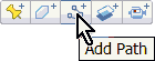 B. Click the ADD PATH icon select the [Style, Color] tab.
- Set the Color to RED or BLUE, something that stands out.
- Set the Width to about 2.0
C. Zoom out so that you can see both your place marker and the tower marker.
|
|
4.2 Show the Elevation Profile

|
|
A. Right-mouse-click on the Line you've just drawn and select Show Elevation Path.
TIP. The profile becomes more accurate as you zoom in on parts of the path line. Double click on sections of the elevation profile to zoom in and load that section of the contour.
|
|
Things to note about the above example:
A. Note the position highlighted red above, at the position of the first hill (obstacle) closest to your location.
This hill is about 14m higher than your location and may obstruct the Line-of-Sight (LOS) to the tower.
B. The distance is only 7.2km which is quite a short distance and will give stronger signal to counter act the effect of obstacles in the path.
This also means that the effect of the earth's curvature will be negligible.
Distances of 26km must take into account the curvature of the earth.
Google Earth does not account of this curvature, so we need to use a more sophisticated calculator .
C. This example Cell Tower is quite elevated in altitude. This will also help with getting signal over obstacles.
|
|
More Accurate Calculations of Signal Strength
|
In this step the Ligo Wave Link Calculator is used
|
|
1. Enter the values in order of importance (refer to default settings list below):
a. Select Metric System
b. Enter Radio Type "Custom" for both TX and RX
c. Enter Antenna Info copy/paste from the ACMA website.
d. Enter Metric copy/paste from your place marker in Google Earth.
e. Enter Latitude and Longitude paste in as Decimal degrees with a "S" or "E" see example/defaults.
f. Enter all other values following the guide below. Note for brevity, Name is not mandatory

1. Press Calculate Link:
The most important result is the Signal Level at RX site.
↑ -51 ~ -73 dBm is Excellent signal, 5/5 bars.
-75 to -83 dBm is Good signal, 3-4/5 bars.
-85 to- 95 dBm is Fair signal, 2-3/5 bars.
-97 to -113 ↓ dBm is Marginal to None 0-1/5 0 bars.
These are typical values which may vary between modem models, For mobile phones these values are generally lower, with good signal down to -105dBm
Some phones such as the iPhone represent signal quality, rather than signal strength via the bar bisplay

|
|
| |
|
| |
|
|
| |
| Acronym |
Description |
Acceptable values |
| RSSI: |
Received Signal Strength Indication
RSSI is a dBm signal strength indicator of the wideband signal for the band to which the device is connected.
RSSI is a value that takes into account both RSCP and Ec/I0.
Calculated as follows:
RSSI [dBm] = RSCP [dBm] – Ec/I0 [dB]
The higher (less negative) the RSSI value,
the better the signal quality.
|
Range (dBm)
|
Rating |
Expected Connectivity |
↑ -51
to -73 |
Excellent |
Should not be affected by cell breathing/loading |
| -75 to -83 |
Good |
Normally no problem.
Should hold a connection, even with heavy cell loading. |
| -85 to- 95 |
Fair |
Workable under good conditions where interference from neighboring towers is not present. Could suffer poor data speeds and occasional dropped connection. |
| -97 to -113↓ |
Marginal |
Low data speeds and regular disconnects due to cell loading/breathing and dropped connections.
|
|
| RSCP: |
Received Signal Code Power
The pilot channel power level received by the mobile handset or modem for the connected cell (code signal) . Different cells using the same carrier are compared using this value to make cell re-election and cell handover decisions.
|
| Ec/Io: |
Energy per chip (Ec)
to total received power (Io) ratio.
This is the ratio between the connected code signal (RSCP) from the cell tower and the total noise, interference from other towers and non code signals (RSSI).
|
Higher (less negative) values can indicate a better signal quality.
However EC/Io is often misleading due to the nature of the interfering signals, and varies with the number uf users connected to the cell.
This value is less than 1 and negative when expressed as dBm.
Calculated as follows:
Ec/I0 [dB] = RSCP [dBm] – RSSI [dBm]
|
| Cell ID: |
The ID number of the Cell tower |
For Fixed Wireless installations, this value should not change.
If Cell ID changes at particular times of the day, especially at peak hour traffic times, this indicates that the tower you normally connect to is over loaded/oversubscribed. |
|
Need more help to determine which antenna will best suit you?
We understand that most people just want to get their Mobile Phone or Mobile Broadband service working without having to learn all about it. Some of our customers are indeed "tinkerers" or "enthusiests" but mostly they just want something that works properly, and get on with life..
So we offer our site survey service to analyse your 3G or 4G services and suggest a recommendation as to which antenna system will be best suited to your requirements and budget.
- We'll find Cell Tower's that service your exact position.
- Examine which towers have 3G, NextG, DC-HSPA+, 4G and 4G MIMO for your carrier of choice.
- Calculate an estimate of the signal you should get and the Antenna System you will need to get it.
Please send us a eBay message to enquire.
Go back to the ONwireless eBay Store
|
|
|